|
|
List of new features and Improvements of GO2cam V6.11.201 , released on 2024 年 3 月 1 日 . 版本生命週期中新增的改進: 修正檔改進 |
|
下表中使用的圖示 |
|
新功能 |
|
改進 |
|
|
網路與服務 |
|
|
|
使用者可以建立帳戶,然後即可存取 透過單一入口提供多項服務 :
此入口網站也提供關於 GO2cam 的有趣資訊和新聞。 位置:說明檔 > 網路入口 已於 2023 年 7 月在 GO2cam V6.10.206 中引入。 |
|
|
|
go2transfer 是 資料檔案傳輸 的服務 GO2cam 終端使用者。 位置:檔案 > go2transfer secured 已於 2023 年 7 月在 GO2cam V6.10.206 中引入。 |
|
|
|
安裝、系統與硬體 |
||
|
|
系統 |
可執行檔 (*.exe 檔案)現在具有 有效的數位簽章 . 此簽章確保了 真實性 和 完整性 可執行檔。可防止防火牆封鎖其安裝。 |
|
|
|
可復原 先前版本的使用者資料 ,例如組態檔案、刀具、tec 檔案、符號等。 位置:工具 > 從其他版本匯入 |
|
|
|
|
現在 GO2cam 中,使用者將透過訊息得知新更新:
|

|
|
|
|
硬體 |
DPI 管理 (每英吋點數) 在 Windows 顯示設定中,您可以修改文字、應用程式等的尺寸至 125%、150% 等。此修改現在已在所有 GO2cam 對話方塊中完美管理。 |
|
|
|
開啟零件 |
相容性:開啟低於 .PCE V5.8 (2008) 的 檔案是不可能的。 |
|
|
|
應用程式介面 (API) |
||
|
|
GO2cam API 已完全更新,將程式語言從 Pascal 變更為 Javascript 。同時也編寫了新的 API 說明檔: GO2cam Javascript API |
||
|
|
許多 新功能 已包含在 API 中:
|

|
|
|
|
新編輯器 您可以透過執行此新編輯器直接在 GO2cam 中編寫腳本。您也可以預覽程式並在畫面上驗證結果。 位置:工具選單 |
||
|
|
新標準巨集: 零件系列 這允許定義具有相似特徵但尺寸略有差異的零件列表,以減少程式設計每個零件所需的工時。右側的影片概述了此巨集。 另一個影片 可在 API 說明檔頁面找到,演示如何建立零件系列組態。 |

|
|
|
|
在 GO2cam V6.10 中,多年來提供的 標準巨集 已從軟體中移除。 我們已 重寫 了這些程式中的大部分,它們現已重新提供。 Javascript 語言;它們已重新提供。 |
||
|
|
圖形使用者介面 |
||
|
|
4. 互動式橫幅提醒您 最新更新的可用性 . |
|
|
|
|
圖形圖表 |
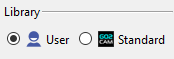
新 GO2cam 標誌用於:
|
|
|
|
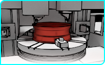
現在使用者可以精確調整 透明度 使用機器樹底部的動態滑桿,不再是開/關選項。 |
||
|
|
工作選單 |
工作選單標籤現在可以容納更多選單(>6): |
|
|
|
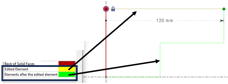
新增了兩種實體顏色。 編輯中的圖素: 正在編輯的圖素變為設定的顏色。 編輯中的圖素之後的圖素: 正在編輯的圖素之後的所有圖素變為設定的顏色。 |
|
|
|
|
此 孔向量的顏色 現在可透過「工具 > 選項 > 主題」中的「實體背面」進行自訂,以配合個人化主題。 主題 的顏色 替代方案 1。 這使得使用者可以根據個人化主題調整顏色以獲得更好的視覺效果。 |
||
|
|
現在可以為曲面的背面添加顏色,以便輕鬆區分它們。 顏色自訂可在「工具 > 選項 > 主題 > 實體背面」中完成。 |
|
|
|
|
新增了用於區分時間單位的持續時間單位:
也允許使用相同的單位但不同的精度!持續時間可以定義為 秒 或 毫秒 . |
|
|
|
|
新 JavaScript 編輯器 已新增於 工具 選單。此 API 允許編寫腳本並改進自動化您的流程。 |
||
|
|
選項有幾項改進: 自訂工具列 選項:
|
|
|
|
|
|
|
|
|
|
幾何一般性 |
||
|
|
如果我們要將實體移動到一個平面,而該選取的平面是在同一實體的面上建立的,則禁止此操作。該平面不會顯示在可能的目標平面清單中。 |
||
|
|
將軸系統移動到軸系統是一個新命令,可協助使用者將任何幾何圖形移動到使用者定義的任何軸集。 |
|
|
|
|
文字對話方塊的介面已更新,採用了 新圖示 並新增了功能,例如:
|

|
|

|
|
線架構幾何 |
||
|
|
對於線架構幾何:當我們編輯一個圖素時,它的顏色以及之後建立的圖素的顏色,可以在「工具 > 選項 > 主題」頁面中自訂。更多資訊請參閱關於 主題 . |
||
|
|
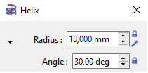
角度 選項已新增至 多邊形 和 螺旋 命令,允許定義圖素的 起始角度 。 |
|
|
|
|
已實施 中點 建立模式已新增至 點 命令。這提供了在兩個點之間確切的 中點距離 建立點的能力;可以是端點、中心點或點。 |
|
|

|
|
線切割 EDM 幾何 |
||
|
|
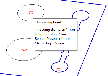
螺紋點 |
當您建立螺紋點時,資訊不再顯示在畫面上。 資訊現在會顯示在 氣球 滑鼠移到螺紋點上方時。
|
|
|
|
工作平面 |
||
|
|
|
|
|
|
|
CAD 介面 |
||
|
|
使用 Interop 的實體匯入: 匯入原生檔案現在支援 讀取孔特徵 來自以下 CAD 系統的
|
||
|
|
SolidWorks 介面 |
可載入 SolidWorks 組態 . 可以同時載入多個組態(例如,一個包含零件的組態和另一個包含素材的組態)。 |
|
|
|
DXF/DWG 匯入 :我們的日誌報告會顯示具有唯一中心的圓形數量。 例如,如果一個檔案包含 20 個圓形,但只有 14 個不同的中心,則表示零件中有 14 個不同的孔。 |
||
|
|
匯入程序已重新設計:
|
|
|
|
|
|
能夠 指派顏色 在 車削自動實體匯入期間 根據實體顏色為輪廓圖素指派顏色。
|
|
|
|
|
|
|
|
|
PMI 中的新功能,用於執行 兩個實體面之間的測量 以修改值。這僅適用於距離和直徑的註解。 |
||
|
|
PMI 類型 已新增至「零件資訊」中
詳細說明了各種類型的 PMI 數量:
尺寸數量(語義)/ 尺寸數量(圖形)/
編輯尺寸僅適用於尺寸(語義) |
||
|
|
新匯入: Rhino CAD 軟體。 檔案格式為 *.3DM。匯入 2D 圖素和實體。 |
||

|
|
孔特徵 |
|||
|
|
使用者孔模型建立 |
|
新命令: 使用者孔管理 此新命令允許進入使用者孔庫,並存取 新模型建立 . |
|
|
|
新對話方塊 視窗已建立,參數與先前版本相同。 參數組織不同,分為 3 個不同的標籤
|
|
||
|
|
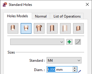
標準孔 & |
在新對話方塊中,我們新增了一個名為「 標準 . 」的標籤。 定義法線方向 它允許 孔的法線方向。您可以指定 X、Y 和 Z 軸的向量方向。預設為 X0 Y0 Z1,位於參考平面的 Z 方向。 |

|
|
|
|
車削中的徑向孔 新增標準孔對話方塊。
|
|||
|
|
車削中的徑向孔 斜面上的孔(車削) |
|||
|
|
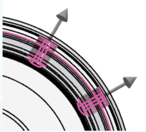
預設方向 同樣,孔的預覽現在可在畫面上動態顯示。 在辨識貫通孔時, |
|||
|
|
此 孔向量的顏色 現在可透過「工具 > 選項 > 主題」中的「實體背面」進行自訂,以配合個人化主題。 主題 的顏色 替代方案 1。 已改進。 |
|
||
|
|
這使得使用者可以根據個人化主題調整顏色以獲得更好的視覺效果。 |
||
|
|
加工特徵 |
型腔 銑削特徵 辨識 可以區分 和 開放 封閉階段 |
|
|
|
加工特徵 |
孔模型庫 ,從而為每個階段建立獨立的特徵。 在辨識視窗中,您現在可以選擇一個 (標準或使用者)。辨識將會為辨識出的孔指派所選庫中的第一個相容模型。 |
|
|
|
加工特徵 |
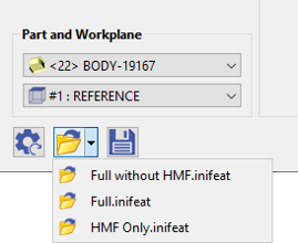
注意:這僅在存在 HMF 套件時適用。
|
|
|
|
加工特徵 |
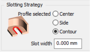
如果「輪廓選擇」選項設定為新模式「輪廓」,則現在可以使用槽加工循環來加工槽特徵。(
|
|
|
|
加工特徵 |
已選擇合適的刀具(如果 opelist 未強制指定刀具) 最小距離計算 (RGMF_SHORTED_DISTANCE): ( 槽加工: ) |
|
|
|
加工特徵 |
最小距離計算不僅限於型腔與島嶼之間,或兩個不同島嶼之間。現在我們也能確定型腔的最窄區域。 儲存組態檔案: ( 槽加工: ) |
|
|
|
在自動辨識視窗中,您可以載入/儲存組態檔案,其中包含要搜尋的特徵類型以及相關的 opelist。這些檔案(副檔名為 .inifeat)儲存在 GO2cam Ini 目錄中。
|
槽 車削中的槽特徵 新命令「
|
|
|
|
車削標籤下的「零件」下新增了「 |
」循環。這會在「槽」特徵中執行指派的 opelist 以加工零件。
新選項,可建立一個 與顏色關聯。 |
|
|
|
車削標籤下的「零件」下新增了「 |
這使得能夠使用單一刀路對整個形狀進行不同進給率的程式設計。 執行循環時,會自動產生用於變更進給率的技術功能。 下刀類型
用於 Zigzag 槽循環: ( Zigzag ) |
|
|
|
車削標籤下的「零件」下新增了「 |
這個新的
( Zigzag ) |
|
|
|
車削標籤下的「零件」下新增了「 |
根據 僅 Z 僅 X 軸向鑽孔
|
|


|
|
刀具直徑 <= 幾何直徑 |
||
|
|
預設直徑由拾取點的位置計算。 重疊方法
|
|
|
|
|||
|
|
|||
|
|
請注意,選項頁面中定義的這些值是預設值,將指派給所有循環的參數:將它們切換為 0 可能很危險! . 產品 立式車削 新產品 在
機器檔案已正確設定;我們已建立新的專用副檔名: |

|
|
|
|
分割零件 和 新增能力 沿 Z 軸,將加工分成 此 多個區域 沿 Z 軸。 |
||
|
|
|
|
|
|
|
選擇, 表格中的值,
|

|
|
|
|
線切割 EDM 切削策略自動套用 零件分析 流程中的新自動化: 到命令辨識的輪廓。 類型學 為此,我們在 的定義中加入了 |

|
|
|
|
策略 有幾種類型可用: 圓柱體的直線切削
|
|
|
|
|
4 軸加工。 對於圓柱體類型,我們還可以選擇一個 可容許直徑範圍 |
||

|
|
,為 0 至 10 公釐、10 至 20 公釐等的孔建立策略。 |
||
|
|
|
在 GO2cam 中時,它會在執行命令時自動選取。您可以在影片中看到它。 當我們有 切削條件 EDM 代碼 已新增至工具頁面。 連結 ID . |

|
|
|
到 材料名稱 |
||
|
|
用於切削條件管理。之前,僅使用材料檔案名稱。 機器檔案 技術表格 |
|
|
|
|
選擇 更簡單。 我們刪除了組合方塊中的兩個項目:技術表格和策略表格。 僅在「序列」模式下才能建立新表格。 多零件加工 (MPM) |
||
|
|
選擇 循環間的退刀 管理 我們在「工件夾具 > 進化」頁面中新增了一個選項,可根據裝置的邊界盒進行退刀。 |
||
|
|
分割零件 |
||
|
|
使用者工作文件 |
|

|
|
|
中斷點 已新增功能。 中斷點 已新增。 NC 檔案 |
||
|
|
允許或不允許操作員使用「GO2cam Operator」修改 NC 檔案。因此,在 GO2cam 中,我們有一個標誌可在操作員的設定檔和權限中啟用或停用。
|
|
|
|
|
FTE(孔特徵 + 持續 ID) |
||
|
|
一個選項允許選擇要載入的組態。可以同時載入多個組態(一個組態包含零件,另一個組態包含素材)
|
匯出 外部連結 的新對話方塊 Vericut / Eureka / Makino 和 事先,必須在工具頁面的選項標籤中提供條碼。 修正檔 - GO2cam V6.12 的修正
If you exit the MTE or NCcontrol simulation, the breakpoints are automatically saved . And when we restart the simulation, they are put back in place. If we save the part , the breakpoints are also kept. |
|
|
|
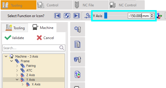
Tooling |
While editing an axis of machine, the value of the axis course is now displayed. |
|
|
|
Link of Axes |
New ability to link two axes together. You can apply this option while creating the machine. In creation of kinematic right-click on an axis and choose ‘ Link a Component ’. The purpose is to pilot two or several axes together. |
|
|
|
Tool numbering |
New possibility to modify the tool number hence changing the position of the tool after tool mounting. You can double click on tool support or right click on tool support then “ Change position ” to have a window to enter new tool support number. The target tool support have to be empty. |
|
|
|
使用者工作文件 |
The comparison function has been added in MTE Control . It is available directly while simulating the machining. When you play the simulation, the comparison is not active, but once you stop the simulation, the comparison is re-calculated. The comparison has also been improved, please watch a video here: 使用者工作文件 |
|
|
|
2 Axis Milling & Shape |
||
|
|
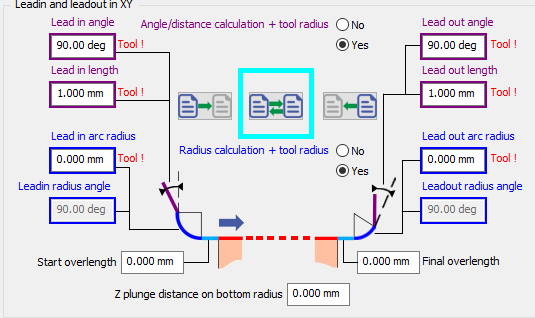
For Manual Operations , a new option has been added that allows to invert the parameters for the leadin and leadout. |
|
|
|
|
Outside angles: Under the options window, new toolpath option for the treatment of outside angles: generate loops . It enables to ensure good quality of corners. This is only possible for center toolpath (not part, compensation) |

|
|
|
|
Lateral passes in contouring Independent Passes is renamed into Compacted Passes. Compacted means that no retract is programmed between passes. The option is not available (grayed out) if the ‘ Part ’ toolpath is chosen: the passes will always be ‘independent’ (not compacted) and always have gain/loss of compensation for each pass. |
||
|
|
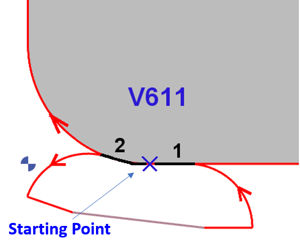
Improvement in the calculation of Overlengths for closed profile with 1st 和 last elements tangent. In V611, the overlengths take into consideration the shape of the profile . Start overlength (1) is tangent to Last Element and final overlength (2) is tangent to first element . |
|
|
|
|
2 new options in the Slotting:
|
|
|
|
|
Plunge Cycles |
We added chip-breaking options in the plunge contour 和 plunge pocket operations . |
|
|
|
新 Leadin Rotation speed In strategy page,the Leadin Depth must have a value , unless Leadin Feedrate and Leadin rotation stay grayed out |
||
|
|
Deep Drill and Clevis cycle have been separated into 2 cycles. Deep Drill has been renamed as Gundrilling. |
||

|
|
3 Axis Milling |
||
|
|
User Interface |
The menu called ‘Multi-Axes Milling’ is now called Shape Milling . It used to include systematically the menus for 4 and 5 axis simultaneous, while now there may be only 3 axis milling operations, due to the new structure of packages. |
|
|
|
Tooling |
此 Lens Mill Cutter is available for more cycles:
|

|
|
|
Tooling |
此 Oval Mill Cutter 和 Barrel Mill Cutter are now available for Z Level operation. |
|
|
|
4-5 Axis Simultaneous |
||
|
|
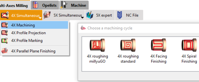
4Xs Cycles
|
Two new cycles have been added:
The submenu has been renamed to " 4X Machining ," encompassing both Roughing and Finishing operations.
You can watch a video presenting the 4Xs Roughing millyuGO operation and how to set it up. From V6.11.202 , you are able to simulate these operations in realistic way by setting OFF the option ‘Simplified Machining’. |
|
|

|
|||
|
|
5 Axis Expert |
|
|
|
The 5X Expert option has now a dedicated menu of same name. It is not anymore a submenu in '5X simultaneous' menu. |
|
|
|
Turning |
||
|
|
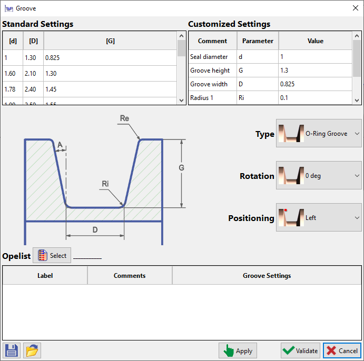
Groove Feature |
New command ' Groove ' has been added under Shaft Creation to automatically design grooves on parts as per related standards and to assign opelists onto them. Also check 在自動辨識視窗中,您可以載入/儲存組態檔案,其中包含要搜尋的特徵類型以及相關的 opelist。這些檔案(副檔名為 .inifeat)儲存在 GO2cam Ini 目錄中。 for additional information. |
|
|
|
Feature |
New ‘ Feature ’ cycle added under ‘Part’ in the Turning tab. This runs the assigned opelist in ‘Groove’ feature to machine the part. |
|
|
|
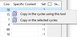
New option that enables to create a table of feedrates associated to colours. When executing the cycle, the techno functions to change the feedrate are generated automatically. It enables to program a single toolpath on a whole shape with differing feedrates. |

|
|
|
|
Now we have a new Plunge type for the Zigzag groove cycle: This new Zigzag option enables the toolpath to simultaneously move into both axes at each step of the toolpath, providing a unique cutting approach.
|

|
|
|
|
New abilities to define pecking directions:
|
|
|
|
|
For manual Drilling operations there is the new ability to preselect the tool by filtering the tool diameter in the selection (same as the milling pocket). The list is reduced to capable tools with Tool Diameter <= Geometry Diameter The default diameter is calculated by the position of the picking point. |
|
|
|
|
Finish Groove operation: With method ‘In groove corner’, we have introduced a new option related to stepover to optimize the toolpath. |
|
|
|
|
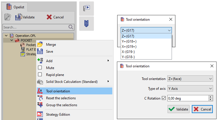
When selecting geometry for the broaching cycle, you can now choose a solid edge instead of just a face (as in 6.10). The selected edge must be linear and collinear with the broaching axis for acceptance. Tool orientation is based on averaging normals of adjacent faces. |
||
|
|
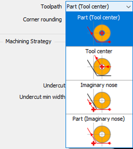
Management of P point in Part mode We have added a new type of toolpath calculation: Part (Imaginary Nose)
|
|
|
|
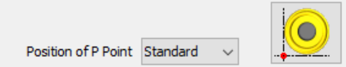
In this situation, we also advise forcing the P Point option directly in the tool page, so that you cannot have 2 different piloted points for the same tool! |
|
||
|
|
In the Chip-breaking management, we added the possibility to define a dwell at each retract. |
||
|
|
The safety parameters defined in Tools>Options>Turning now accept the value 0 . This is dedicated to users who are used to design the leadin and leadout motions. Those values defined in the Options page are the default values that will be assigned to the parameters of all cycles: please note that it might be dangerous to switch them to 0! |
||

|
|
Vertical Turning |
||
|
|
Product |
New product Vertical Turning :
|
|
|
|
走心式加工 |
||
|
|
New ability to slice the part in Z axis, to divide the machining in several areas along Z. Right-click on Material in the Machining tree to get access to the function.
When you validate there is no visible change in the geometry. These information are considered only during the application of an automatic opelist. |
|
|
|
|
Wire-Cut EDM |
||
|
|
New automation in the process: Cutting Strategies are automatically applied to the profiles recognized by the command. For this, we added the concept of Typology into the definition of Strategies . Several types are available:
For the typologies of cylinders, we also have the ability to select a range of admissible diameters , to create strategies for holes from 0 to 10 mm, from 10 to 20 mm, etc. |
|
|
|
|
When we have only one solid in GO2cam, it is automatically selected while running the command. You can see it in the video. |
||
|
|
Cutting Conditions |
EDM code is added in the tools page. It is now taken into account if defined to link an ID to a material name for cutting conditions management. Before, the name of the material file was used only. |
|
|
|
Machine File |
The selection of Techno Tables is more simple. We deleted 2 entries of the combo box: Techno Table and Strategy table The creation of new tables is available only with mode ‘Sequences' |
|
|
|
Multi-Parts Machining (MPM) |
||
|
|
Machine File |
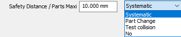
Management of retracts between cycles We added a new option in the page Work-Holding Device>Evolution, to retract according to the device bounding box. |
|
|
|
User Workshop Document |
|
|
|
Barcode is added in 3D window under Tool type. Beforehand, the barcode must be given in the tool page, in Options tab. The barcode is exported in the document as a bar. |
|
|
|
事先,必須在工具頁面的選項標籤中提供條碼。 |
||
|
|
使用者工作文件 |
使用者工作文件 function has been added. |
|
|
|
Breakpoints |
Breakpoints have been added. |
|
|
|
NC File |
Possibility to allow or not the modification of NC file inside NC Control for operators using "GO2cam Operator". So, in GO2cam we have a flag to activate or not in the operator's profiles & rights. |
|
|
|
GO2cam for SolidWorks |
|
|
|
匯入 |
New possibilities with Solidworks :
|
|
|
External Links |
|
|
|
Export |
New dialogs for Vericut / Eureka / Makino |