咬合限制 - 軸向銑削:
藍線用於定義咬合面的停止曲面。
我們可以旋轉這條線,得到較高的邊緣線和斜角支臺。

目標也是減少加工時間 - 藍線必須靠近區域。
|
正確 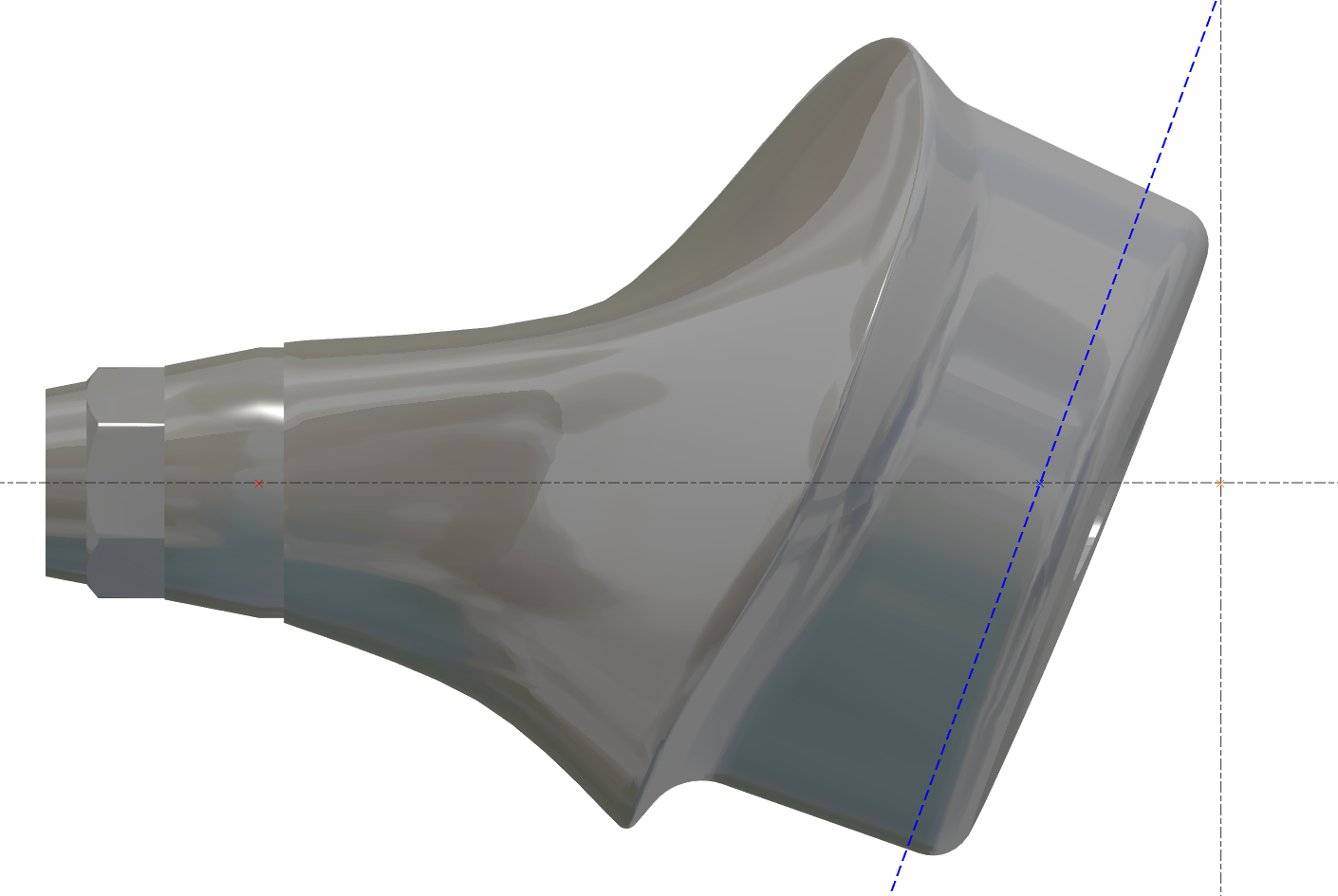
|
不正確 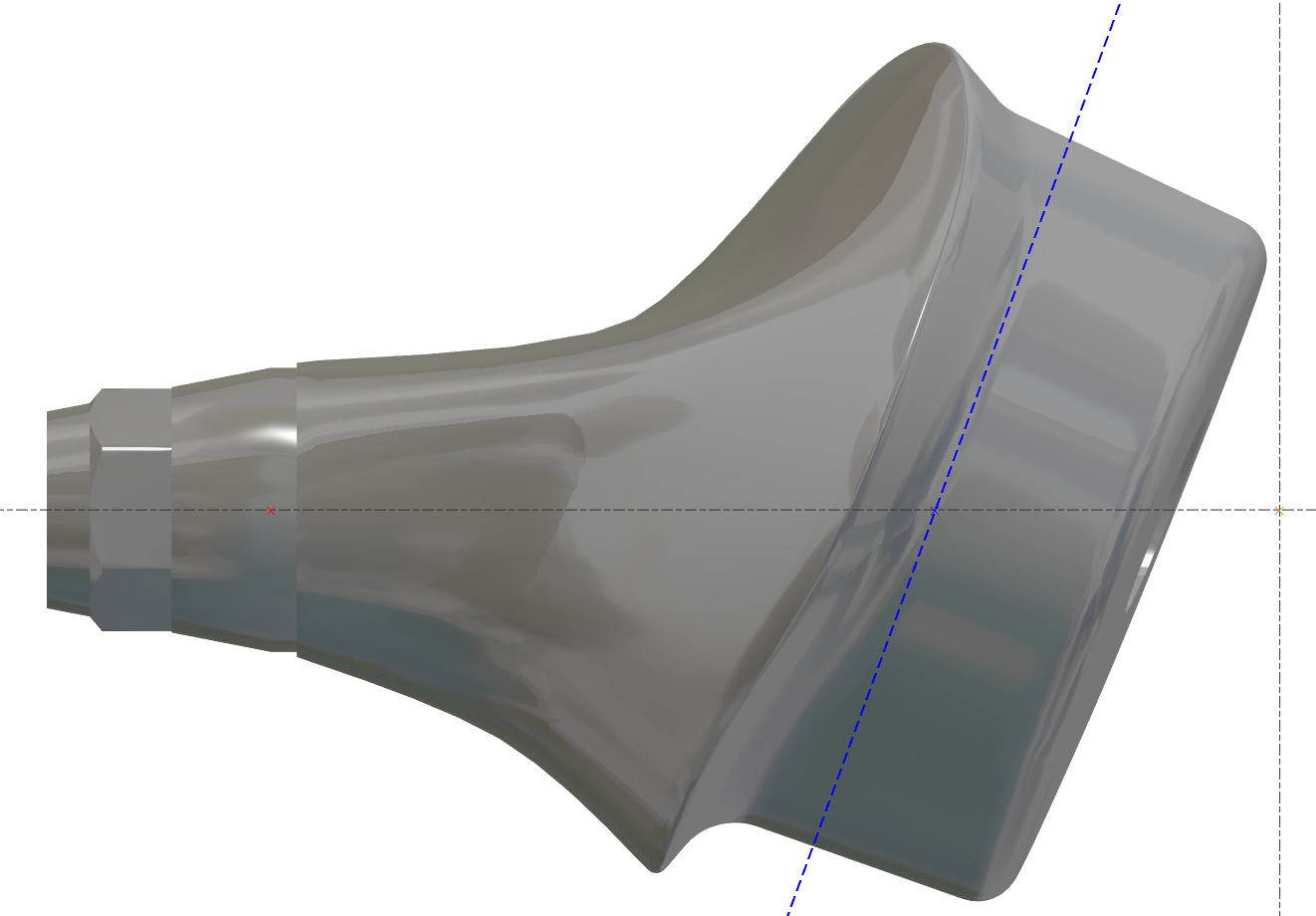
|
|---|
更改素材直徑 - 應用程式內錯誤
機器值內部必須是最大值,然後我們可以更改它
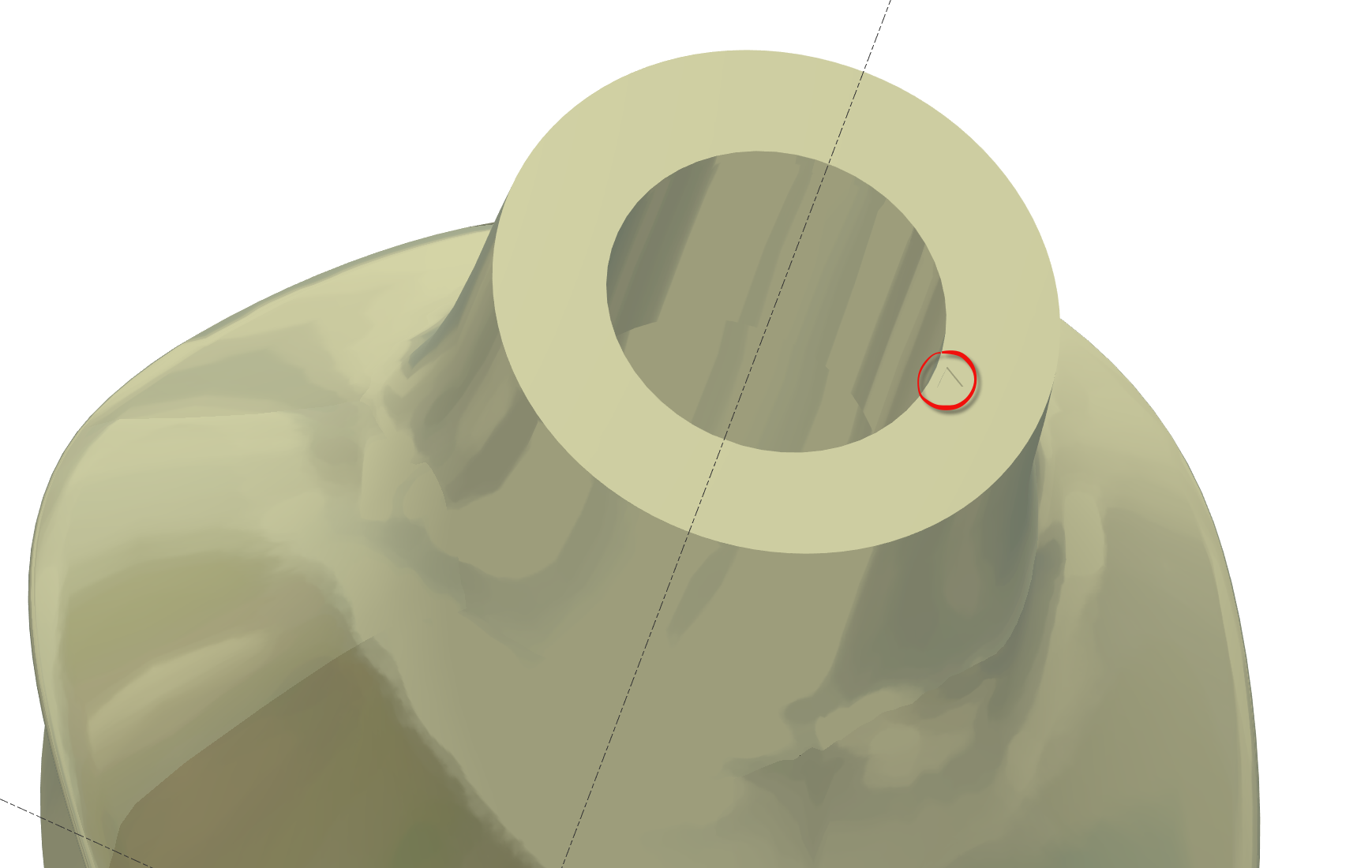
無連接的支臺
有些STL檔案沒有連接,但我們必須確保對齊是正確的。
無連接的支臺在底部表面有“小三角形”以指示參考位置
需要預定義視圖嗎?
有些使用者想要預定義視圖,這取決於每個使用者。
我們可以有3個預定義視圖。
使用者必須創建這些視圖。
將零件移動到正確的“預定義”視圖 N°1,然後按 CRTL+F2
將零件移動到正確的“預定義”視圖 N°2,然後按 CRTL+F3
將零件移動到正確的“預定義”視圖 N°3,然後按 CRTL+F4
然後使用視圖,按 F2 或 F3 或 F4
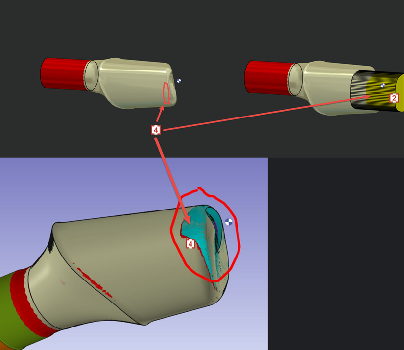
側邊表面的邊緣有殘料嗎?
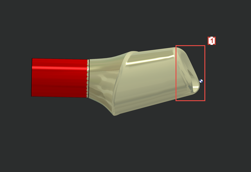
We don't want 4XS toolpath in this area of occlusion [1] .
4軸刀路會導致刀痕和不良的表面品質。
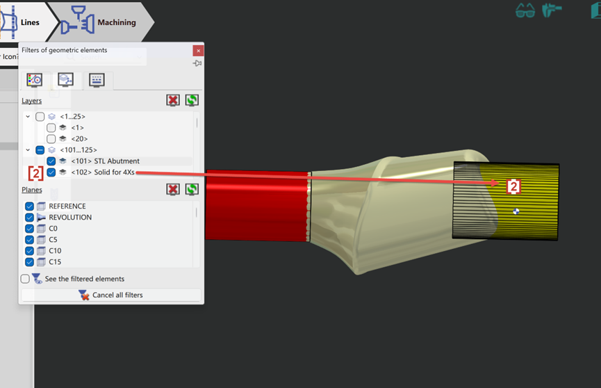
So we will create solid layer 102 [2] to prevent 4xs toolpath to contact and damage the occlusion surface on STL.
Now the 4xs toolpath [3] will not touch solid layer 102 [2] and so the occlusion surface [1] which is wrapped by layer 102 is protected.
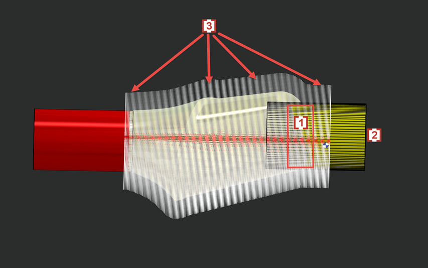
In some cases layer 102 will also cause some rest material in the edge of side surface [4] which is also wrapped by solid layer 102 [2] .