用於程式編寫加工操作的幾何圖形選擇是一個複雜的主題。
幾乎每個加工選單都有其獨特的方法和特性。它也取決於幾何圖形的類型,是線架構還是實體。
您可以在此找到許多資訊:
輪廓線與刀具路徑的方向
一般而言:
-
For milling, the G17 ( Z+ Plane) is the default setting. It defines the working plane where the X and Y axes determine the toolpath. Imagine a flat surface where the machine moves the cutting tool across the length (X) and width (Y).
-
對於車床加工,預設設定為 G18 (Y+ 平面)。在此,刀具路徑由 X 和 Z 軸定義。簡單來說,刀具沿著材料的長度 (X) 和深度 (Z) 移動。
所選輪廓的方向決定了刀具路徑的位置(右/左)。請參閱下方銑床零件的範例:
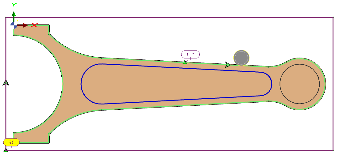
對於開放式挖槽,刀具位於輪廓線的左側(順時針)
|
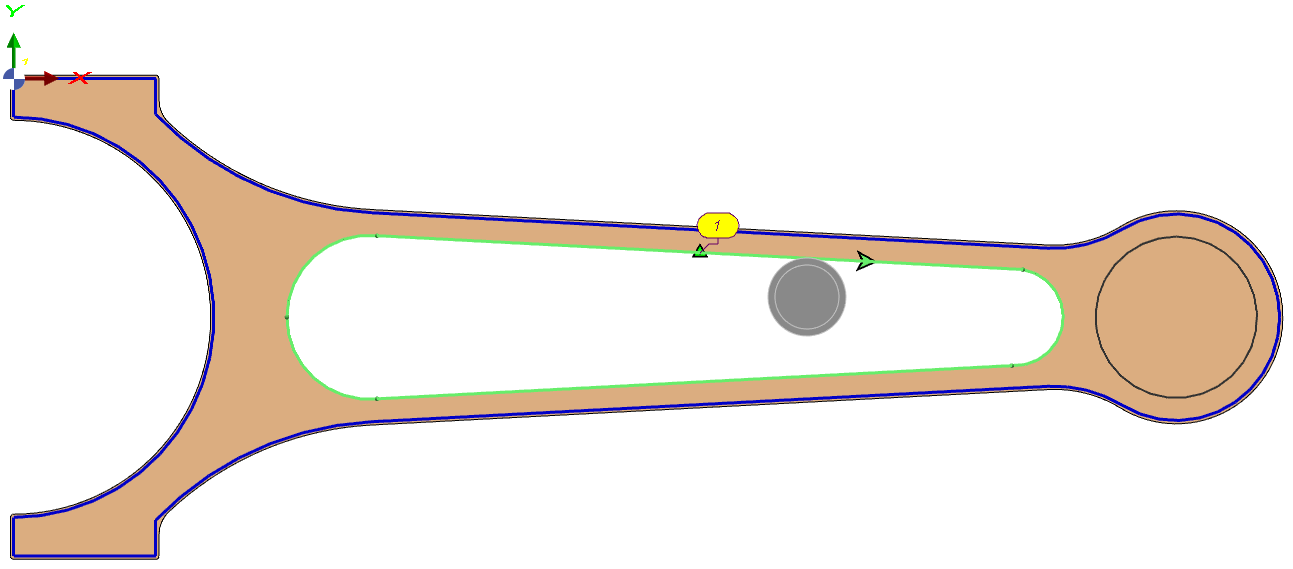
對於內部挖槽,刀具位於輪廓線的右側(順時針)
|