介紹

|
對於某些機台,錐度的程式設計只能在 4 軸加工中進行。在此情況下,您首先使用此指令建立錐度。之後,使用 4 軸幾何圖形指令自動產生加工所需的頂部和底部輪廓,位於任何所需的 Z 高度。 |
此功能有 2 個不同的用途(因此有 2 個不同的名稱):
-
在 線切割放電 ,建立將作為第二個幾何輪廓的線框圖形,用於 4 軸模式加工 .
-
在 銑床加工 ,建立基於錐度建立的實體,準備好進行 Shape 工法加工 .
如何使用此功能
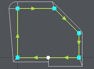
1. 點擊定義錐度的輪廓。
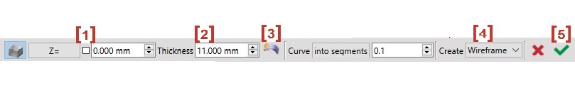
2. Type in the altitude [1] used when creating the taper.
3. Type in the thickness [2] of the part.
4. Choose the direction [3] of the part relative to the altitude chosen.
5. Click on the last button [4] 以選擇 實體建立 或 線框建立 .
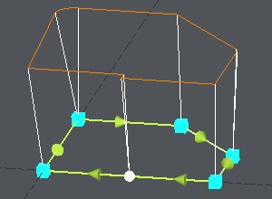
結果會根據您填寫的參數進行預覽。
6. Click on the green tick [5] when the result shown is the one you want.
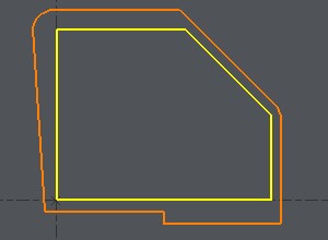
範例:
您想使用 4 軸循環加工此形狀。填寫參數並檢查預覽(此處為橘色)是否正確。
|
|
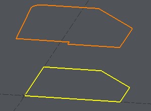
點擊綠色勾號,即可建立幾何圖形並準備加工。
|
|