咬合面限制 - 轴向铣削:
蓝线用于定义咬合面的停止曲面。
我们可以旋转这条线,我们有高边距线和斜基台。
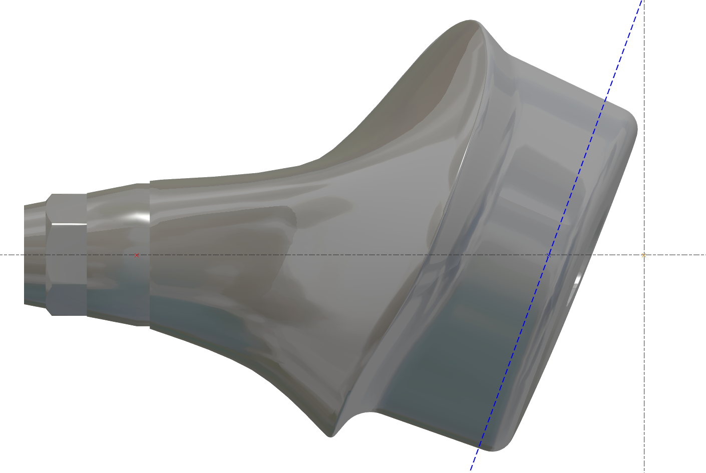
目标也是减少加工时间 - 蓝线必须靠近区域。
|
正确 
|
不正确 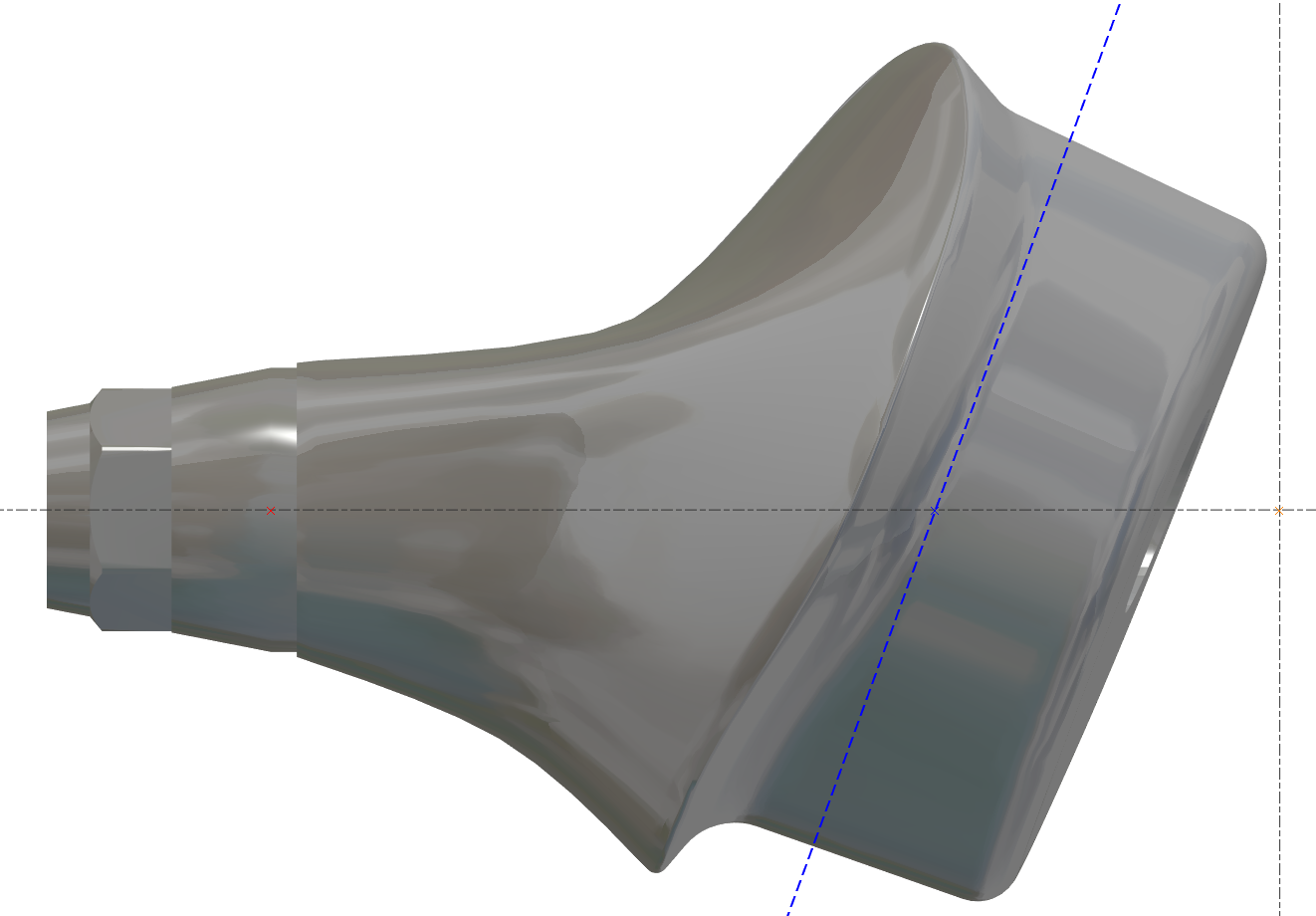
|
|---|
更改毛坯直径 - 应用程序内部错误
机器值内部必须是最大值,然后我们可以更改它
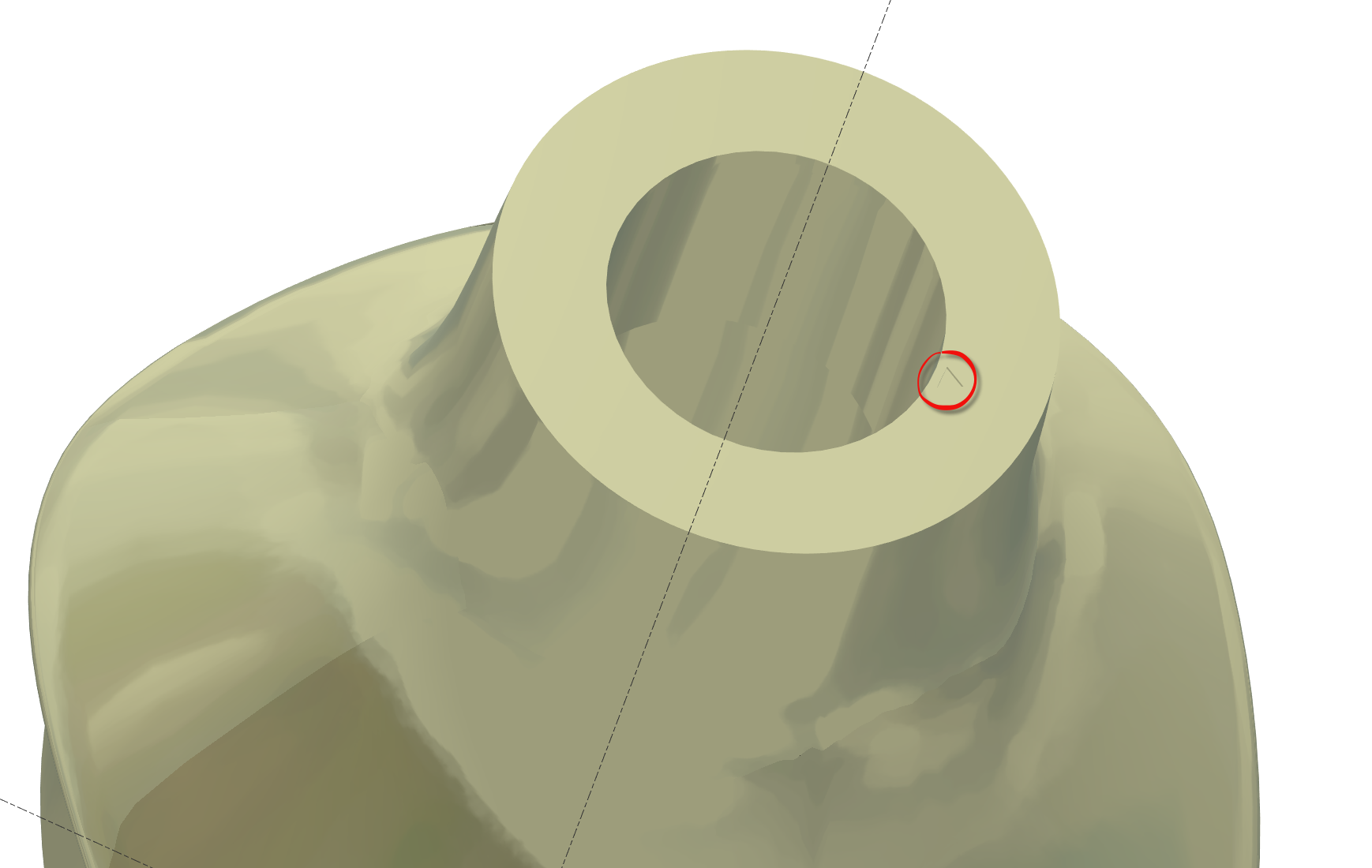
无连接的基台
一些STL文件没有连接,但我们必须确保对齐是正确的。
无连接的基台底部有一个“小三角形”表示参考位置
需要预定义视图吗?
一些用户想要预定义视图,这取决于每个用户。
我们可以有3个预定义视图。
用户必须创建这些视图。
将零件移动到正确的“预定义”视图 N°1 然后按 CRTL+F2
将零件移动到正确的“预定义”视图 N°2 然后按 CRTL+F3
将零件移动到正确的“预定义”视图 N°3 然后按 CRTL+F4
然后使用视图按 F2 或 F3 或 F4
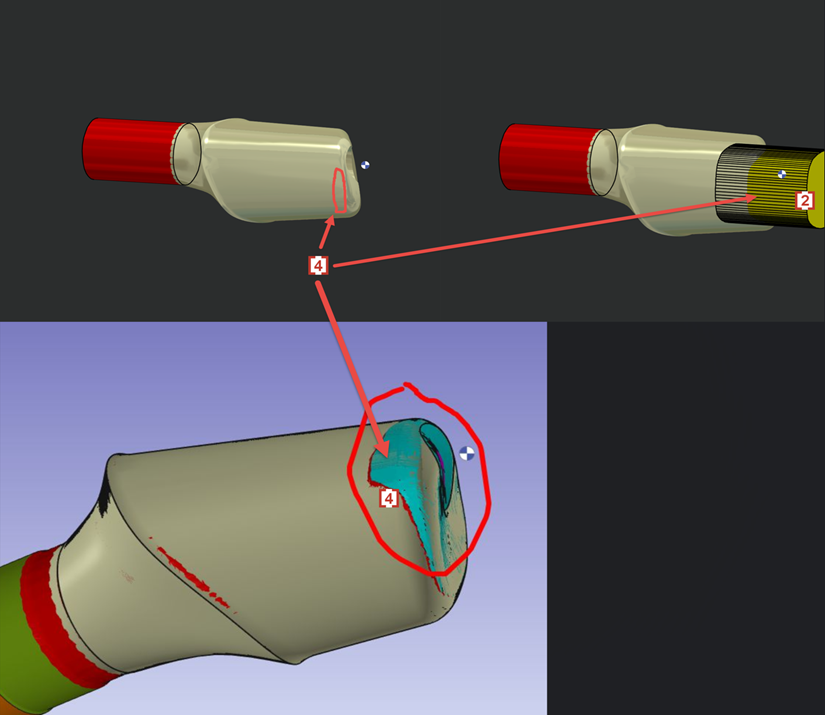
侧面剩余材料在边缘?
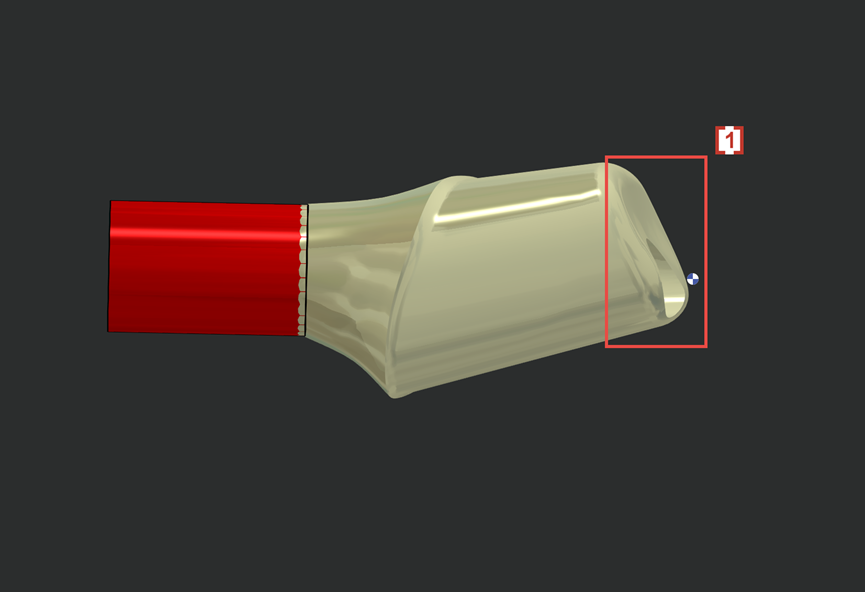
We don't want 4XS toolpath in this area of occlusion [1] .
4轴刀路会导致刀痕和糟糕的表面质量。
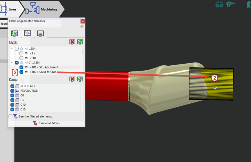
So we will create solid layer 102 [2] to prevent 4xs toolpath to contact and damage the occlusion surface on STL.
Now the 4xs toolpath [3] will not touch solid layer 102 [2] and so the occlusion surface [1] which is wrapped by layer 102 is protected.
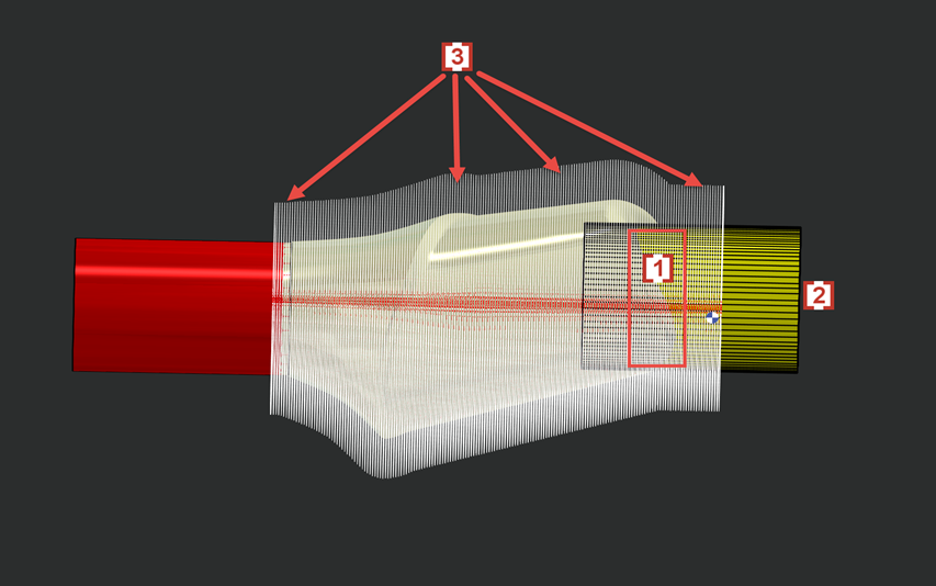
In some cases layer 102 will also cause some rest material in the edge of side surface [4] which is also wrapped by solid layer 102 [2] .