介绍

|
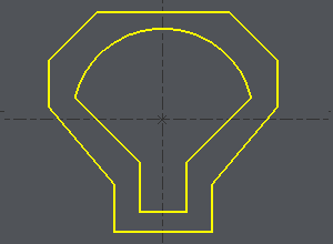
同步点位于要加工的2个轮廓上,用于强制线在4轴模式下在它们之间移动。 |
同步点的定位有3个步骤:
-
定义2个轮廓
-
进行一次输出以检查是否需要同步点
-
使用自动、手动或组合模式定义同步点
定义轮廓
1/ 定义轮廓
绘制一个选择框或依次单击2个轮廓。
在元素中间定义起点,如图所示:
-
单击轮廓,
-
单击起点元素,沿元素移动光标,然后单击需要起点的位置,或通过单击按钮选择元素的中点或起点:此处选择中点
-
单击终点元素(示例中为同一元素),沿元素移动光标,然后单击需要终点的位置,或通过单击按钮选择元素的中点或终点:此处选择中点。
|
|
2/ 输出
-
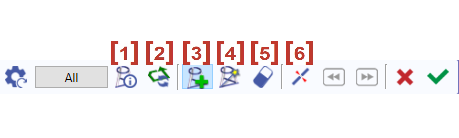
Once the profiles are done, the dialog bar appears : Click on About the profile [1] . A message box give you the characteristics of the 2 profiles selected, number of elements, number of synchro points.
3/ 定义同步点
|
|
关于轮廓 |
|
|
反转所选轮廓的方向 |
|
|
添加同步点 - 手动创建同步点 |
|
|
在2个区域之间自动创建同步点。单击按钮“ 全部 ”,所有轮廓的创建都是自动的。 |
|
|
通过单击同步点来删除它。 |
|
|
切割元素 |
单击绿色勾号“ 其他轮廓 ”进行确认,或在另外2个轮廓上创建同步点。
单击红色叉号取消所有已创建的同步点。
创建同步点时,我们可以结合手动和自动创建。这就是第二个示例所解释的。
自动方法
|
Click on [1] . There are 7 elements on a profile and 11 in the other one. It can be machined with the cycle 4 axes contour/contour but it is not optimized. If you want to optimize the toolpath, you have to set up synchro points. |
|
|
The synchro point can only be defined on existing points or elements extremities. You have to cut an element : click on [6] and then click on the arc, you can move the cursor all along the element, click on the screen when you want to cut. A circle (tangency) or a square (sharp angle) is displayed where you cut. |
用白色光标切割圆弧 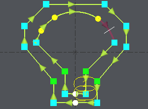
|
|
The number of elements is now the same on the 2 profiles : Click on [4] ,然后单击“ 全部 ”,2个轮廓的所有端点都成对连接。 |
同步点自动创建 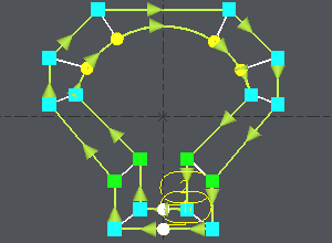
|
手动和自动方法结合
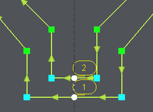
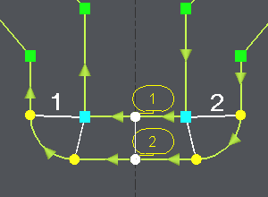
让我们以一个相同的示例,但增加2个角。这里我们需要创建双同步点,这在自动模式下是不可能的:
|
Click on [1] to have information about the 2 profiles. |
|
|
Click on [3] , click on the angle (blue square) and click on an extremity of the corner (yellow circle), click again on the angle (blue square), a message warns you about the creation of a double synchro point, click on OK and click on the other extremity of the corner (yellow circle). 对另一个角重复相同的操作。 |
|
|
The synchro point can only be defined on existing points or elements extremities. You have to cut an element : click on [6] and then click on the arc, you can move the cursor all along the element, click on the screen when you want to cut. A circle (tangency) or a square (sharp angle) is displayed where you cut. |
|
|
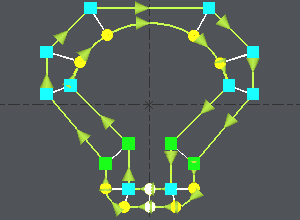
We want to create synchro points between the 2 corners already treated : click on [4] ,单击已定义的2个同步点( 1 和 2 在图像上)以限制要处理的区域,2个轮廓的所有端点都成对连接。 |
Once the synchro points are set up, click on [1] to obtain information for the synchro points created , if the machining is possible you are told about it. Then you can go to the machining editor and choose the cycle 4 axes cnt/cnt.