用于编程操作的几何图形选择是一个复杂的主题。
几乎每个加工菜单都有其自身的方法和特性。它也取决于几何图形的类型,线框或实体。
您可以在此处找到许多信息:
轮廓线和刀具路俓的方向
总的来说:
-
For milling, the G17 ( Z+ Plane) is the default setting. It defines the working plane where the X and Y axes determine the toolpath. Imagine a flat surface where the machine moves the cutting tool across the length (X) and width (Y).
-
对于车削,G18 (Y+ 平面) 是默认设置。在此,刀具路俓由 X 和 Z 轴定义。简单来说,刀具沿着材料的长度 (X) 和深度 (Z) 移动。
所选轮廓线的方向决定了刀具路俓的位置(右/左)。请参见下面的铣削零件示例:
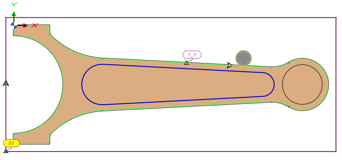
对于开放式挖槽,刀具位于轮廓线的左侧(顺时针)
|
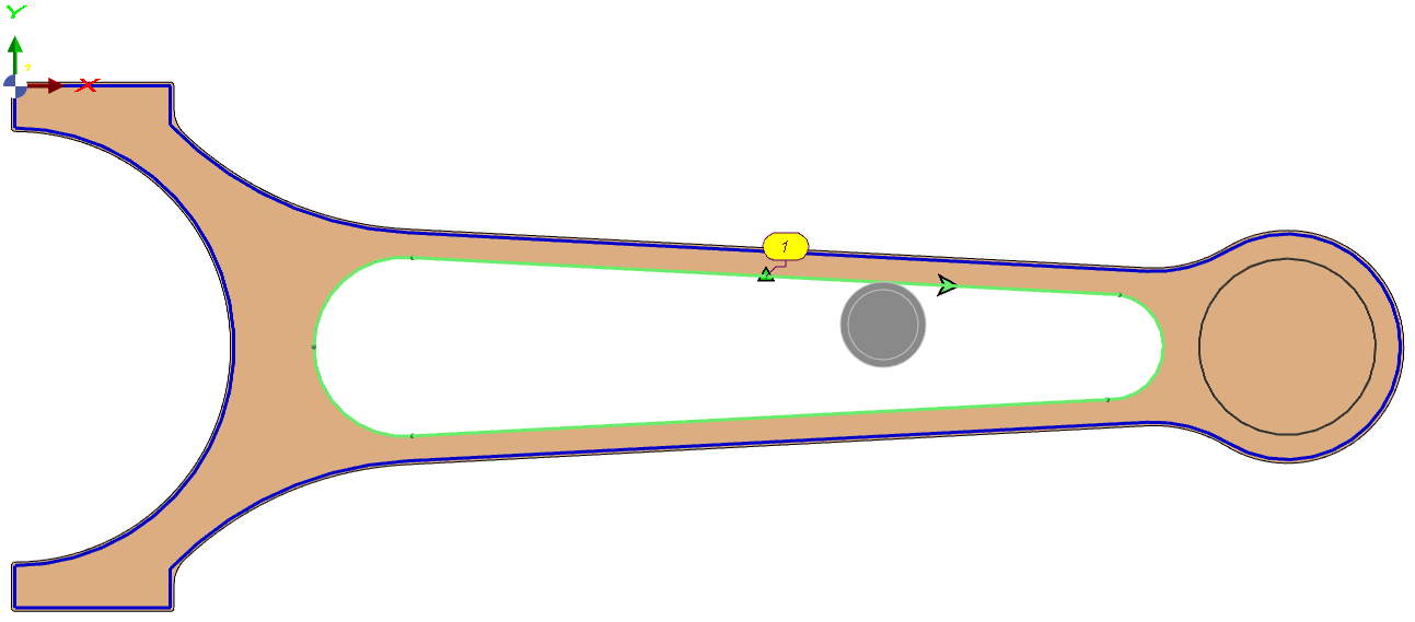
对于内部挖槽,刀具位于轮廓线的右侧(顺时针)
|